“Know how to solve every problem that has been solved.”“What I cannot create, I do not understand.”— Richard Feynman
Photolithography: Printing with a Low-Pass Filter
Semiconductors
⛓
What you need to know first
1 concepts, 1 layers
The requisite-knowledge inventory for this page, bottom-up: the
primitives at the base, combined upward until you reach what this page
assumes. Skim the layers you already own; start wherever the ground gets unfamiliar.
base
The Fourier transformconcept
↳you are here
1 of these are concepts without a dedicated page yet —
the grey chips. Following the linked ones first makes the rest land.
Every feature on every chip you own was printed with light whose
wavelength is larger than the feature. The machine that does it —
a projection scanner — is optically just a very good camera, and a camera
obeys diffraction: its lens accepts only the spatial frequencies that fit
through the pupil. That makes the whole of photolithography one sentence
long. A projection lens is a low-pass filter on the mask's
spatial-frequency content. Fourier transform the mask, delete
everything with ∣f∣>NA/λ, transform back,
square: that is the image the resist sees. This page runs that model —
fifteen lines of numpy — and gets the resolution limit, the death of sharp
corners, phase-shift masks, and the reason OPC exists, each validated
against a number known in advance.
def image_1d(mask, dx, na, lam=193.0): """Coherent aerial image of a mask amplitude. The entire imaging model.""" E = np.fft.fft(mask) f = np.fft.fftfreq(mask.size, d=dx) E[np.abs(f) > na / lam] = 0.0 # the pupil: a hard low-pass filter return np.abs(np.fft.ifft(E)) ** 2def image_2d(mask, dx, na, lam=193.0): E = np.fft.fft2(mask) fx = np.fft.fftfreq(mask.shape[1], d=dx) fy = np.fft.fftfreq(mask.shape[0], d=dx) FX, FY = np.meshgrid(fx, fy) E[np.sqrt(FX**2 + FY**2) > na / lam] = 0.0 return np.abs(np.fft.ifft2(E)) ** 2
Numbers used throughout: ArF excimer laser,
λ=193 nm; numerical aperture
NA=0.9 (dry) and 1.35 (water immersion — the
fluid's n=1.44 is what lets NA exceed 1). One scope
statement before anything else: this is coherent imaging
(illumination coherence σ=0, a single plane wave).
Real scanners use partially coherent illumination — Hopkins (1953) is the
standard formulation — which raises the ultimate grating cutoff by a
factor (1+σ) and softens every hard edge in the story
below. The structure of the physics is unchanged; the coherent case is
the one you can hold in your head.
The resolution limit, measured
A line/space grating of pitch p has diffraction orders at
spatial frequencies m/p. Coherent imaging needs the
±1 orders to interfere with the zeroth: the moment
1/p>NA/λ, they fall off the pupil and the
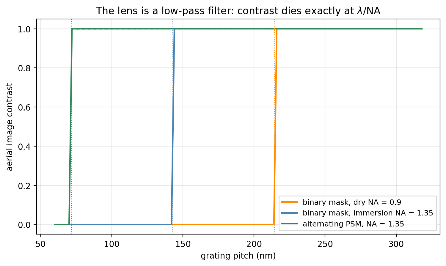
image goes uniformly gray. Not gradually — exactly:
The all-or-nothing step is itself the signature of coherent illumination:
a grating prints at essentially full contrast or not at all. (Partial
coherence turns the cliff into a slope — that is most of what it does.)
The measured collapse pitches sit within one 2-nm grid step of
λ/NA, and immersion buys exactly its
advertised factor: 216 nm → 144 nm is
0.9/1.35 to three digits.
The green curve is the trick worth the whole page. Levenson's
alternating phase-shift mask (1982) etches every other
transmitting slot to add a half-wave of path — multiplying that slot's
amplitude by −1. The mask's average transmission is now zero:
the DC order vanishes, the fundamental moves to
1/2p, and the two surviving orders interfere to print the
pattern at half the binary cutoff — measured 72 nm
against a theoretical 71.5, a factor of 2.00 below the binary mask
through the same lens. In half-pitch terms,
k1=HP⋅NA/λ drops from
0.50 to 0.25 — the hard floor. Nothing about the lens changed; the mask
stopped wasting an order on carrying zero information.
What the filter does to corners
A sharp corner is made of arbitrarily high spatial frequencies, and the
pupil discards all of them past the cutoff. So corners round — not from
any imperfection, but from information that provably never reached the
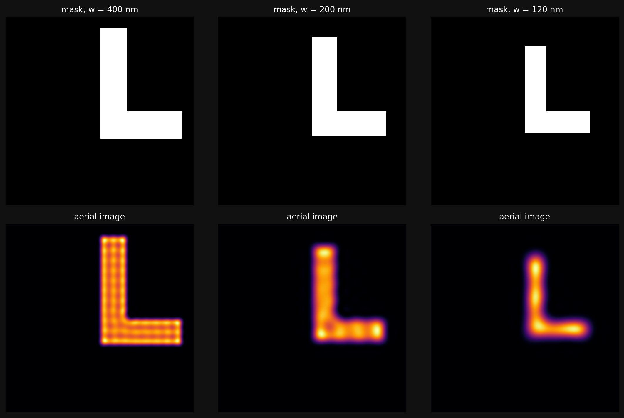
wafer. The same L-shaped elbow at three linewidths, imaged at
NA = 1.35:
At w=400 nm the print is faithful, down to the faint
standing-wave ripple along the arms (interference of edge diffraction —
real, not an artifact). At 200 nm the outer corner has visibly melted. At
120 nm — still above the 72 nm half-pitch limit! — the elbow is a
rounded glow. Resolution limits and pattern fidelity are different
budgets: you run out of corner long before you run out of pitch.
Neighbors matter: proximity
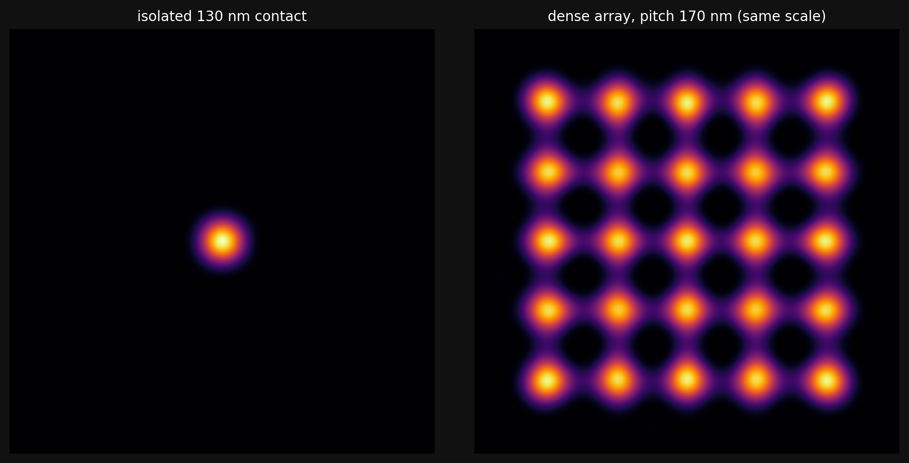
== contacts (130 nm holes, NA = 1.35) ==isolated hole peak intensity 1.659, center of 5x5 dense array (pitch 170 nm) 1.568saddle between adjacent dense holes = 0.341 (22% of peak - resist threshold decides merge)
The same 130-nm contact hole prints differently alone and in a crowd —
each hole's diffracted field overlaps its neighbors'. The number to watch
is the saddle: midway between adjacent dense holes the intensity
reaches 22% of the peak, and the resist threshold below sits at 35%. The
holes stay separated — with a margin of 0.017 in normalized dose. Every
layout rule that forbids certain pitches is this calculation, run in
reverse.
The resist is a threshold detector
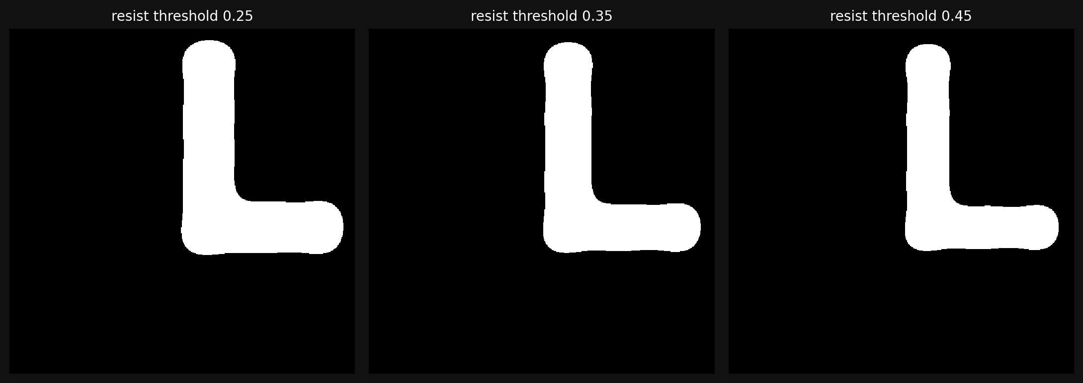
To first order, chemically amplified resist develops wherever the
delivered dose crosses a threshold — so the printed pattern is the aerial
image binarized at a level set by exposure dose. Slide the threshold and
the printed linewidth slides with it:
== dose latitude (elbow arm drawn 160 nm) ==threshold 0.25: printed CD = 156 nmthreshold 0.35: printed CD = 142 nmthreshold 0.45: printed CD = 130 nm
A 160-nm drawn line prints at 156, 142, or 130 nm as the threshold moves
from 0.25 to 0.45 — about 13 nm of critical dimension per 10% of dose.
That sensitivity is dose latitude, one axis of the process
window every fab lives inside; the steeper the aerial image's sidewalls,
the less the CD cares about dose, which is why image contrast — not just
resolution — is the currency of the whole field.
Why OPC exists
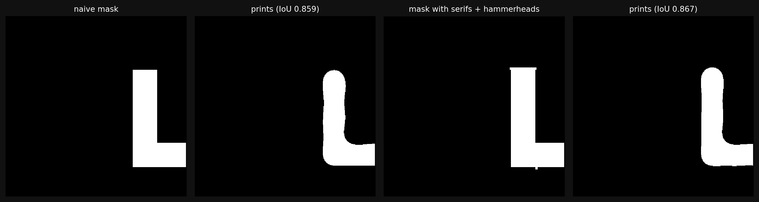
If the lens is a known filter, you can pre-distort the mask so the
filtered result lands closer to the intent — optical proximity
correction. The classic hand moves: serifs on outer corners and
hammerheads on line ends. Here is a one-parameter version:
scan the serif size, keep the best.
Two lessons in one table. First, the wins are local: global pattern
fidelity (intersection-over-union against the drawn target) barely moves,
because corners and ends are slivers of total area — but the line-end
pullback, which is the actual electrical failure mode (a via missing
its landing), goes from 10 nm short to 4 nm long. Hammerheads do exactly
the job they were invented for. Second, more correction is not better:
serifs past 0.2 w actively hurt, overprinting more than they fix. Greedy
hand-tuning saturates within a percent — which is why production OPC is
an inverse problem solved by optimization over every edge
segment of the layout (inverse lithography technique treats the mask
itself as the unknown in exactly the sense of
gradient descent). The
forward model being differentiable — it's an FFT and a mask — is what
makes that industry possible.
The k₁ ladder: forty years on one axis
The whole history of lithography compresses into the Rayleigh scaling
CD=k1λ/NA: shrink the
wavelength, grow the aperture, and grind k1 down with mask
and illumination tricks. Representative production points:
Generation
λ (nm)
NA
half-pitch
g-line (Hg lamp)
436
~0.5
~500 nm
i-line (Hg lamp)
365
~0.6
~350 nm
KrF excimer
248
~0.8
~130 nm
ArF dry
193
0.93
~90 nm
ArF immersion
193
1.35
~38 nm
EUV
13.5
0.33
~13 nm
Check the last ArF row against this page: 38 nm half-pitch at NA 1.35 and
193 nm is k1=0.27 — below our coherent limit of
0.5 and a hair above the absolute floor of 0.25. Production got there by
stacking exactly the tricks demonstrated above: partial coherence and
off-axis illumination for the (1+σ) factor, phase
shifting, aggressive OPC, and finally printing one layer as two
interleaved exposures when a single pass could not. EUV at 13.5 nm
reset λ by 14× so k1 could relax again —
at the price of an optical system with no transparent materials left
(see the probes).
Try First
Each prompt asks a checkable question about the working code or math
above — predict an output, derive a sign, state an invariant, find a
bug. Commit to an answer before clicking "reveal." That commitment is
the whole point: if your answer matched, you understand the piece you
were looking at; if it didn't, that's the part worth re-reading.
predict
The grating vanished abruptly below pitch λ/NA.
Predict: does a single isolated line narrower than
λ/2NA also vanish from the image?
answer
No — it prints dim and wide, but it never disappears. Only
periodic patterns have a hard cutoff, because their spectrum is
discrete: when the ±1 orders leave the pupil there is nothing left
but DC. An isolated feature has a continuous spectrum, and the pupil
always passes the low-frequency part — what you get is roughly the
lens's point-spread function, a blob of width
~λ/2NA regardless of how narrow the
line was drawn. Resolution limits are statements about
distinguishing neighbors, not about detecting lone objects.
why does this work
Why does putting water between the lens and the wafer improve
resolution? The wavelength in water is shorter — is that the right way
to say it?
answer
It's the same fact in two vocabularies. NA = nsinθ:
the lens's exit cone is fixed by geometry
(sinθ<1), so with air the pupil can never accept
spatial frequencies beyond 1/λ. Water's
n=1.44 compresses the wavelength in the medium, letting
rays at the same angles carry 1.44× finer patterns onto the resist —
equivalently, letting NA reach 1.35. Same physics as oil-immersion
microscopy, run in reverse (printing instead of viewing), and worth a
full process generation without changing the laser.
what if
EUV machines use curved mirrors — six or more of them — and the mask
itself is reflective. Why did lenses disappear?
answer
At λ=13.5 nm every material absorbs: there is no
transparent lens material, and even air is opaque (the beam path is
vacuum). Imaging must be done with multilayer Bragg mirrors —
~50 alternating Mo/Si layers, each a quarter-wave thick, reflecting
~70% at best. Six mirrors at 70% each deliver ~12% of the light,
which is why EUV sources chase kilowatts of plasma emission from
laser-blasted tin droplets to get milliwatt-class dose at the wafer.
The low-pass-filter model on this page still applies verbatim — a
mirror pupil is still a pupil.
Extensions
Partial coherence — Hopkins (1953): integrate the coherent image over the source's angular extent; the cutoff stretches by (1+σ) and the contrast cliff becomes a slope. Off-axis (annular, dipole) illumination is source engineering in the same model.
Defocus — multiply the pupil by eiπλzf2 and watch the process window shrink into the dose-focus ellipse every fab plots.
Inverse lithography — treat every mask pixel as a parameter and descend on pattern error through the differentiable forward model; connects to gradient descent and the continuous-relaxation theme.
Where the wafer goes next — the printed pattern masks the dopant diffusion and etches that build the junctions in the PN junction page; the gates those junctions form are the subject of the computer architecture section. This page is how those gates get drawn.
Reproduce it
scripts/gen_photolithography.py regenerates every figure and
number in seconds — the model really is a handful of FFTs. The script's
history is worth a sentence: its first version reported gratings printing
25% past the diffraction limit, because non-commensurate grating
periods leaked spectral sidelobes under the pupil. The fix (integer-pixel
periods, windows an exact multiple) is documented in the source — a
reminder that in Fourier-based simulation, the leakage you forgot about
is always the physics you think you discovered.